
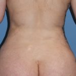
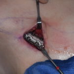
I structure the custom jawline implant design process around one central principle: design toward a defined postoperative facial shape, not toward an implant thickness. The core concept is: implant geometry is the translation of an aesthetic goal into a safe, stable, anatomically blended 3D skeletal shape, with the largest augmentation where change is needed and progressive feathering where it should disappear.
Phase 1 — Define the patient’s desired face before designing the implant
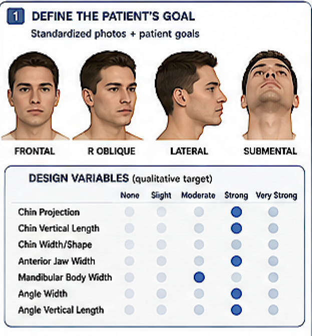
Capture standardized frontal, right/left oblique, right/left lateral and submental images. Using the patient’s reference images make changes to their photographs and,with some back and forth, create structural changes that approximate the patient’s goals. (target setting) Separate changes produced by skeletal contour from changes that depend on fat, skin, masseter, hairstyle, lighting or other non-skeletal variables. This distinction is important because visual targets may contain features an implant cannot reproduce through skeletal augmentation alone.
Then breakdown the desired changes using seven independent design variables:
|
Region |
Primary variable |
|
Chin |
horizontal projection |
|
Chin |
vertical length |
|
Chin |
width/shape |
|
Anterior jawline |
lateral width |
|
Mandibular body |
width + inferior-border contour |
|
Jaw angle |
lateral width |
|
Jaw angle |
vertical length / angle position |
Then assign each variable one of five qualitative targets: none / slight / moderate / strong / very strong.
The qualitative descriptor should eventually be translated into millimeters in CAD, but I would deliberately not have the patient choose millimeters. Patients select an appearance; the surgeon translates appearance into skeletal dimensions.
Phase 2 — Separate the three components of the problem
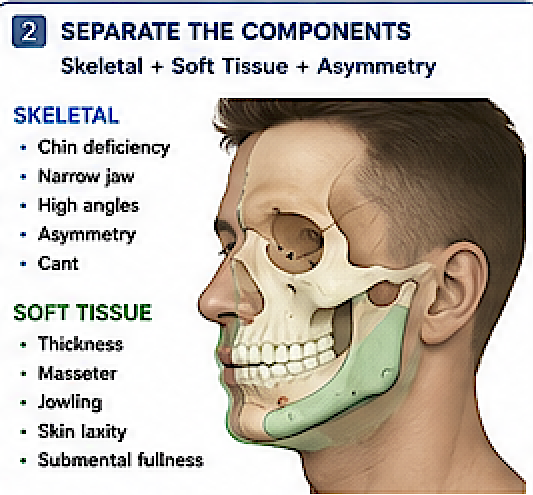
Before implant design, classify what is creating the patient’s current appearance:
Skeletal deficiency + soft-tissue characteristics + asymmetry.
That prevents a common design error: trying to correct a soft-tissue problem by making the implant larger.
In facial asymmetries there is a distinction between skeletal and soft-tissue asymmetries. The bone framework alone may not create perfect visible symmetry.
I would document these separately:
Skeletal
- chin AP deficiency
- chin vertical deficiency/excess
- narrow chin
- narrow mandibular body
- narrow angles
- high angles
- lower-border deficiency
- ramus/angle asymmetry
- chin deviation
- mandibular cant
Soft tissue
- thin vs thick envelope
- masseter prominence/asymmetry
- jowling
- submental fullness
- skin laxity
- scar tissue or prior surgery
Non-implant-correctable skeletal problems
- meaningful occlusal cant
- major mandibular rotation
- significant functional/occlusal discrepancy
It should also be noted that major occlusal or functional discrepancies as problems an implant should not be expected to correct.
Phase 3 — Establish the CT-derived skeletal data
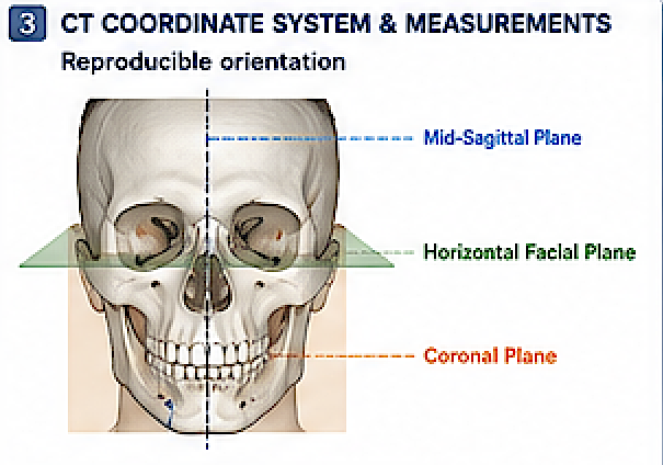
Use a thin-slice CT/appropriate high-resolution scan at 0.5–1.0 mm slices is the preferred basis for custom facial implant design. Most cases are oriented to the same reproducible coordinates
Mid-sagittal plane: cranial/facial midline independent of chin deviation.
Horizontal facial plane: standardized cranial reference
Coronal reference: perpendicular to the other two.
This makes not only a well oriented scan but also one that its useful for comparison to subsequent scans if needed for revision or additional implant augmentations
Phase 4 — Create a “target augmentation map”
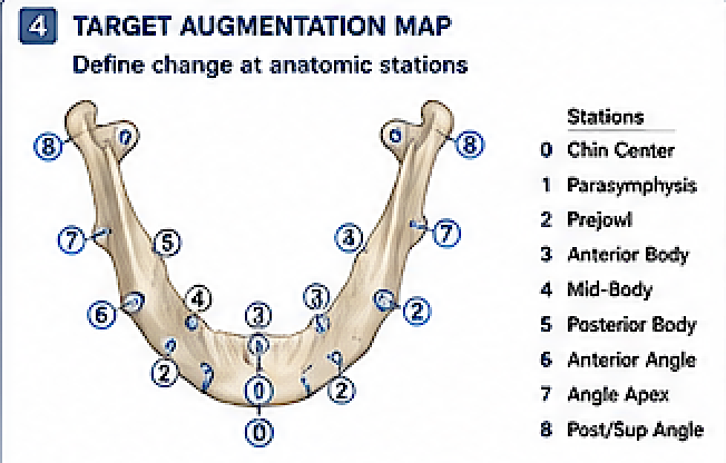
Create a 3D augmentation map of the mandible.
Divide each side into reproducible stations:
0 — chin center
1 — parasymphysis
2 — prejowl
3 — anterior body
4 — mid-body
5 — posterior body
6 — anterior angle
7 — angle apex
8 — posterior/superior angle
At each station record three possible vectors:
L = lateral augmentation
V = vertical/inferior augmentation
AP = anterior/posterior augmentation
So a design could conceptually be documented as:
|
Station |
L |
V |
AP |
|
Chin |
2 |
3 |
7 |
|
Prejowl |
2 |
2 |
0 |
|
Mid-body |
3 |
3 |
0 |
|
Posterior body |
4 |
5 |
0 |
|
Angle |
6 |
8 |
-1 |
Those aren’t suggested values—they illustrate the language.
Now every design change becomes explicit:
“Angle width +1.5 mm bilaterally” is much more reproducible than “make the angles a little stronger.”
Phase 5 — Design contour first, implant second
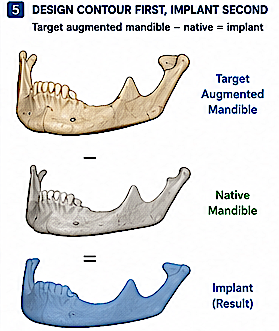
Create the desired augmented mandibular envelope.
Only after the desired skeletal envelope is satisfactory should the software generate/subtract the native mandible to derive the implant volume.
Conceptually:
Target augmented mandible ? native mandible = implant volume
That idea has precedent in published patient-specific facial implant workflows; one computer-aided PEEK workflow described creating a subtraction volume and then iteratively altering implant geometry in response to soft-tissue simulation.
It also aligns with the concept that the implant should create the intended projection, width, vertical length and transition zones rather than merely be “bigger.”
Phase 6 — Treat chin, body and angle differently

I would not use a universal implant-mm ? facial-mm conversion.
There is published evidence illustrating why. In a small six-patient series of PEEK mandibular PSIs, postoperative soft-tissue gain relative to implant thickness differed substantially between chin and angle regions—about 109% at the chin versus approximately 66% at the angle.
That study is much too small to turn those percentages into an a concrete design rule, but it demonstrates something important:
6 mm of implant at the chin and 6 mm at the angle should not automatically be expected to create equivalent visible 6-mm changes.
The masseter, tissue thickness, skin envelope, location and direction of augmentation all matter.
Phase 7 — Explicitly manage asymmetry
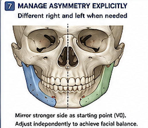
Do not automatically make the implant geometrically symmetric.
For asymmetric faces, first determine whether the goal is:
skeletal symmetry,
visible facial symmetry, or
intentional preservation of some asymmetry.
These are not necessarily the same.
Mirroring the stronger side can provide a useful starting target, in which digital mirroring with differential horizontal and vertical augmentation for asymmetric jaws.
But I would treat mirroring as V0, not as the answer.
A patient could require:
Right implant = +4 mm
Left implant = +2 mm
even though a symmetrical implant would be easier to design.
True customization may mean different right- and left-sided thicknesses to create perceived symmetry.
Phase 8 — Review every design in five mandatory views
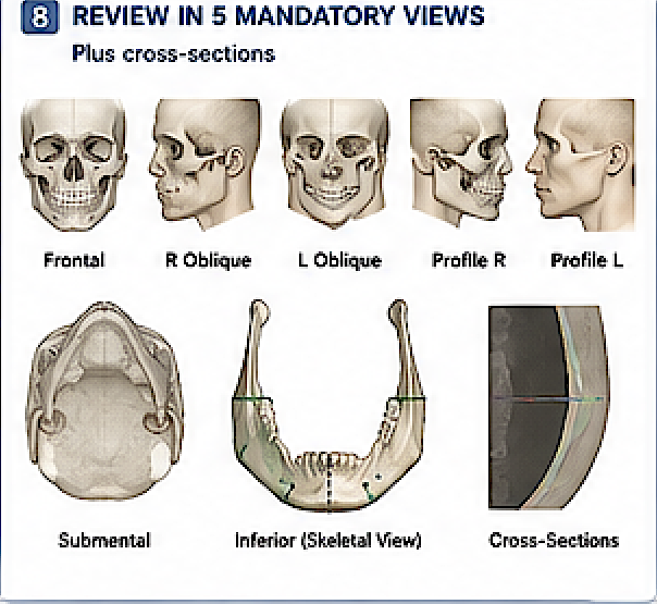
I would never approve a jawline implant from the 3D skull view alone.
Every design review should contain the same images:
Frontal: overall width, chin width, angle width, lower-border symmetry.
Profile R/L: chin projection, vertical chin length, mandibular plane and angle descent.
Three-quarter R/L: body-to-angle transition and posterior jaw prominence.
Submental: actual horseshoe geometry, anterior-to-posterior widening and asymmetry.
Inferior skeletal view: implant footprint and inferior-border extension.
Then add cross-sectional slices at chin, prejowl, body and angle. (3D viewer file)
This is where many apparently attractive 3D designs reveal excessive thickness or abrupt transitions.
Phase 9 — Add two quantitative CAD outputs
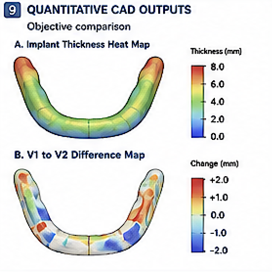
1. Implant-thickness heat map
A color map showing implant thickness over its entire surface.
This immediately exposes localized “hot spots,” unintended asymmetry and abrupt changes.
2. V1-to-V2 difference map
Whenever a revision is made, overlay the two designs and show exactly where material was added or removed.
Instead of:
“Here is revision 3.”
the surgeon sees:
- +1.5 mm lateral angle
- ?1 mm mid-body
- +2 mm vertical posterior border
- unchanged chin.
This would make design revision dramatically faster.
Phase 10 — Introduce a soft-tissue prediction layer, but label it correctly
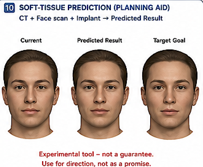
If you can integrate a 3D face scan with CT geometry, the ideal future system is:
CT skeleton + external facial surface + candidate implant ? predicted postoperative facial surface.
Finite-element facial modeling is increasingly sophisticated; a 2026 publication describes nearly automated patient-specific facial models incorporating bone, skin, fat and muscles for preoperative simulation.
However, I would not present current simulation as a guarantee. Even mandibular finite-element methodology lacks broad consensus and robust validation across models.
So I would display it internally as:
Predicted contour — experimental planning aid
rather than:
Expected postoperative result.
Phase 11 — Run a mandatory “surgical reality” review
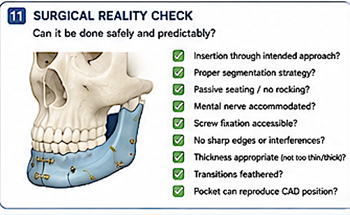
Before approval, mentally perform the operation. An implant that cannot realistically be inserted is a failed design regardless of how good it looks digitally.
The final CAD review should therefore answer:
- Can it be inserted through the intended approaches?
- Is the segmentation strategy appropriate?
- Can the implant be oriented unequivocally?
- Does it seat passively?
- Are there areas likely to catch on bone during insertion?
- Is the mental nerve region accommodated?
- Can screw fixation be performed comfortably?
- Does any border become excessively thin and fragile?
- Does any border become thick enough to be visible/palpable?
- Are transitions appropriately feathered?
- Can the intended pocket actually reproduce the CAD position?
That becomes the Surgical Feasibility Gate.
Phase 12 — Separate the design into three approval gates
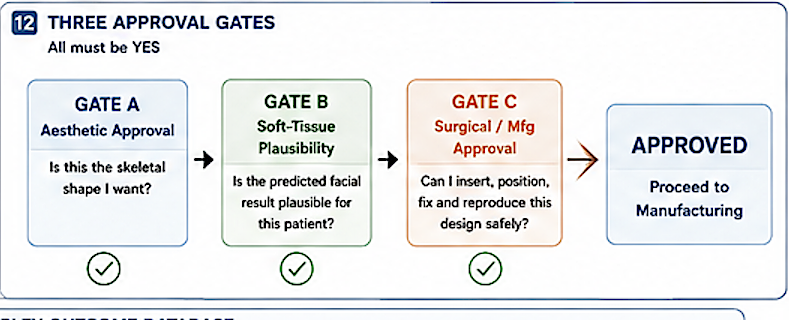
Instead of a single “approved” click, I’d establish:
Gate A — Aesthetic approval
“Is this the skeletal shape I want?”
Gate B — Soft-tissue plausibility
“Given this patient’s tissue envelope, is this skeletal change likely to produce the visual effect we want without obvious over/undercorrection?”
Gate C — Surgical/manufacturing approval
“Can I insert, position, fix and reproduce this design safely?”
Only after all three are YES does it proceed to manufacturing.
Dr. Barry Eppley
Plastic Surgeon