
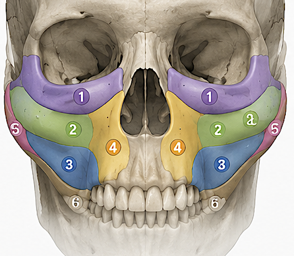
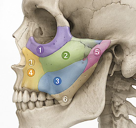
For a custom integrated midface implant intended to create the visual effect of midface advancement, I’d divide the construct into six itheoretical nteracting zones rather than treating it as one uniformly thick shell.
|
Zone |
Design objective |
Contour concept |
Critical constraints |
|
1. Infraorbital rim / anterior maxilla |
Correct negative vector, tear-trough skeletal deficiency, and upper-midface retrusion |
Smooth anterior augmentation beginning below the rim; maintain a continuous rim-to-cheek curvature rather than a discrete “rim implant” |
Protect infraorbital neurovascular anatomy; avoid excessive superior projection that changes lower-lid support unpredictably |
|
2. Malar / zygomatic body |
Establish cheek apex and lateral skeletal framework |
Apex should be individualized in AP and lateral dimensions; generally blend medially into infraorbital augmentation and inferiorly into submalar zone |
Avoid creating excessive bizygomatic width when the real deficiency is AP projection |
|
3. Submalar / anterior maxillary surface |
Fill the concavity below the malar eminence and connect cheek to paranasal augmentation |
Broad, low-gradient augmentation rather than a focal bulge; this is often the “bridge” that makes the entire midface read as advanced |
Overfilling can erase normal ogee contour and create a heavy midface |
|
4. Paranasal / pyriform |
Increase apparent central midface and maxillary projection; support alar-base/paranasal contour |
Greatest augmentation often belongs on the anterior maxillary/paranasal surface rather than the lateral cheek when the objective is simulated advancement |
Feather carefully at pyriform margin; avoid unwanted nasal-base widening or obvious implant edges |
|
5. Lateral transition |
Make malar augmentation disappear into native zygoma |
Long, progressively thinning taper toward lateral zygomatic surface/arch |
A short termination creates a visible or palpable step |
|
6. Inferior transition |
Not a viable zone |
|
|
1. Infraorbital zone
I would make this primarily an anterior projection zone, not simply a vertical thickening of the orbital rim.
The contour should start with the desired relationship among the globe, infraorbital rim, and malar surface. In a negative-vector patient, the implant can bring the skeletal envelope anteriorly while establishing a continuous convexity from the infraorbital rim into the upper cheek. Patient-specific orbital implants have demonstrated the value of designing directly from CT-derived anatomy, although the overall evidence base remains heterogeneous and largely lower-level.
A useful CAD principle is to divide this area further into:
INFRA-U: immediately adjacent to the infraorbital rim. Keep contour changes conservative and smooth.
INFRA-I: lower anterior maxilla beneath the rim. This can carry more of the apparent advancement because adding volume here moves the facial surface forward without creating an unnaturally prominent orbital rim.
The infraorbital foramen and nerve corridor should be explicitly segmented in the planning model, with the implant relieved around it rather than allowing the final design to be determined simply by Boolean subtraction at manufacturing.
2. Malar zone
The malar portion should answer two separate questions:
How much anterior projection is needed?
and
How much transverse width is actually needed?
Those are frequently conflated.
For a patient who looks midface-retrusive but already has adequate facial width, I would emphasize anterior zygomatic-body projection and minimize lateral extension. Conversely, a genuinely narrow zygomatic framework may benefit from an additional lateral vector.
The malar apex should not necessarily correspond to the point of maximum implant thickness. Instead, design the implant against the desired final skeletal surface and allow thickness to result from the difference between native and target surfaces.
Conceptually:
native CT surface ? desired facial skeletal envelope ? implant = difference
rather than:
native surface + arbitrary 4-mm implant.
That distinction is one of the major advantages of a PSI.
3. Submalar zone
This may be the most important transition in avoiding a classic “cheek implant” appearance.
A traditional malar implant frequently creates a focal convexity followed immediately by native submalar concavity. For a midface-advancement effect, I would instead use the submalar component to create a broad transition between:
malar apex ? anterior maxilla ? paranasal region.
The goal is not to eliminate all submalar concavity. A slight concavity is aesthetically useful. The objective is to prevent the augmented malar segment from sitting visually on top of a retruded maxilla.
The recent integrated-PSI series is particularly relevant because its anatomical scheme explicitly divides the midface into upper/lower paranasal, upper/lower infraorbital, malar, and submalar subunits, supporting exactly this multi-zone approach.
4. Paranasal / pyriform zone
For a design intended to mimic maxillary advancement, I would put considerable attention here.
Cheek augmentation alone can make the zygomas look stronger while leaving the central midface retruded. Paranasal augmentation shifts the visual center of the midface forward.
I would separate it conceptually into:
Upper paranasal: lateral nasal wall / upper pyriform region, blending toward the infraorbital segment.
Lower paranasal: anterior maxilla adjacent to the lower pyriform aperture and alar-base region.
The lower portion can strongly influence the apparent projection of the central maxilla and nasal base, so small contour differences can have disproportionate soft-tissue effects.
I’d avoid designing this as a simple crescent sitting beside the pyriform aperture. Instead, make it part of the continuous anterior-maxillary surface extending toward the submalar area.
5. Medial transition
The medial boundary should essentially vanish into the pyriform/nasal-maxillary skeleton.
A common CAD problem is maximizing implant footprint because the technology makes it possible. More coverage isn’t automatically better. At the medial edge, the implant should reach only as far as necessary to generate the target contour.
Think:
full correction ? decreasing correction ? zero correction
across a long enough distance that the soft tissue doesn’t reveal the endpoint.
The same philosophy applies superiorly near the orbital rim.
Overall projection map
For a patient with adequate facial width but global midface retrusion, my conceptual heat map would look roughly like this:
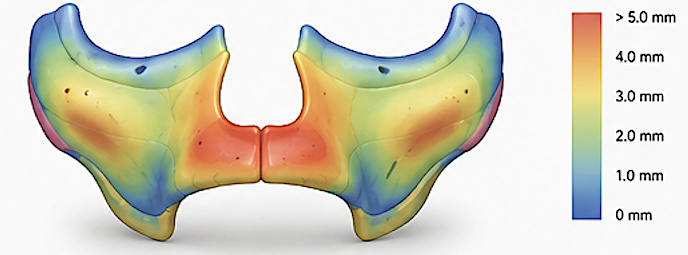
Paranasal/anterior maxilla: high AP emphasis
Infraorbital-anterior maxilla: moderate-high AP emphasis
Malar body: moderate AP emphasis
Lateral zygoma: low-moderate transverse emphasis
Submalar: moderate blending volume
Peripheral transitions: progressively near-zero
That tends to produce an “entire midface forward” impression instead of “larger cheek implants.”
Dr Barry Eppley
Plastic Surgeon :